I’m trying something different this time, a kit from Vantopia! I’m not the world’s best woodworker and needed some help.
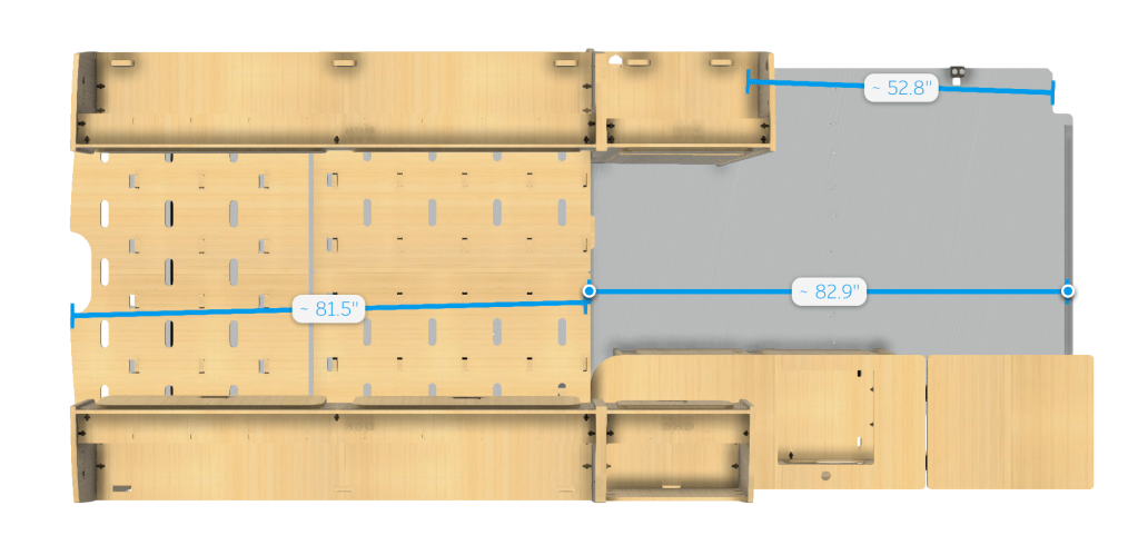
The overall plan is simple, install the kit and put in a desk in the blank space:
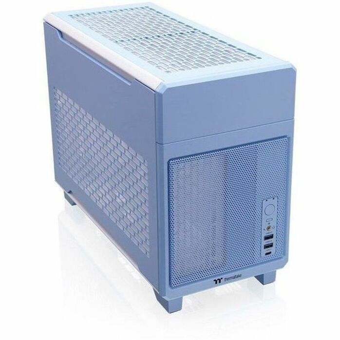
The AW3423DWF I use is 32″ wide, leaving 20″ free on the desk, perfect to put the TR100 build next to:
They are sending extra cabinets to put over my desk, one will house the Raspberry Pi for Home Assistant and comms gear, the rest will be for storage.
The passenger seat will swivel, giving some lounging space to the passenger.
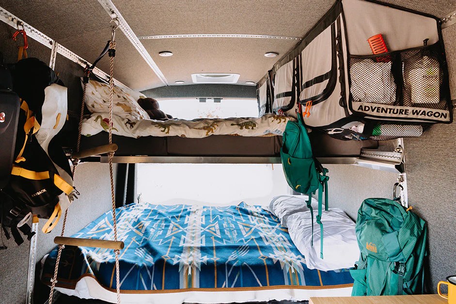
The mattress space is an olympic queen size, which is 66″x80″, which provides 6″ more width vs a queen, but still 10″ shorter than a King. I think it should be just about perfect for the van.
A traverse bed would be smarter and save a bit of space, however, this kit doesn’t have the option to and I’m telling myself that extra insulation and garage space is a good thing
I mean, it is pretty much half of the floorspace for the bed, but what’s another 14″?
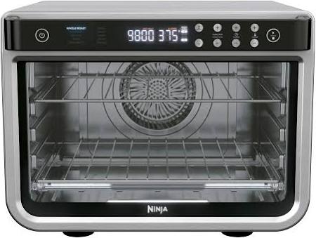
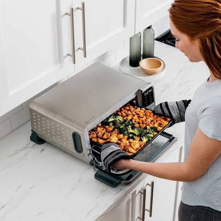
Finally for the kitchen, I’ll slap in the induction cooktop and figure out some sort of electric oven.
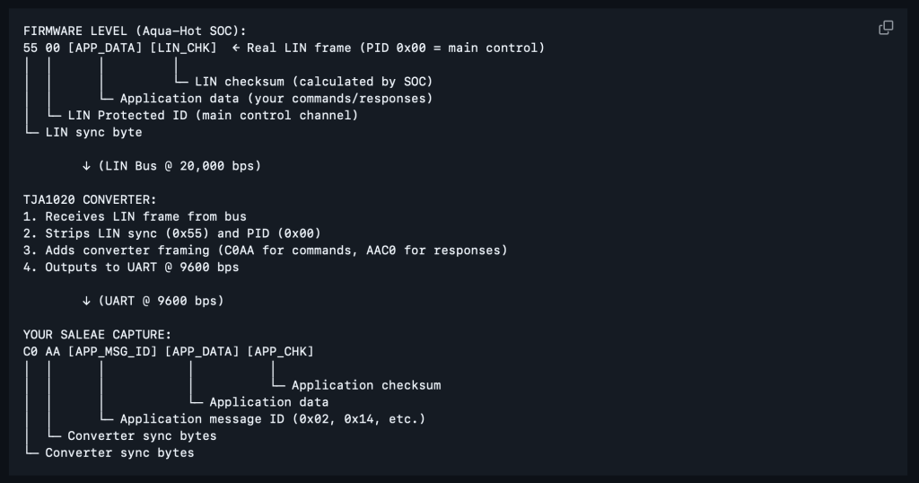
First off, LIN is 12V and it’s pulled low for bytes. The Logic 8 analyzer is 20V~ tolerant, but doesn’t work well over 5V. So, I used a LIN to UART converter board, and BOOM! Data.
Second, I figured out that the microcontroller had BLE so I got curious and downloaded the JP Heater “MyBluee” app and what do you know, the Airxcel Combi is just a rebranded JP Heater, or comes from the same factory JP Heater sources theirs from.
I also noticed the app has built in firmware updating
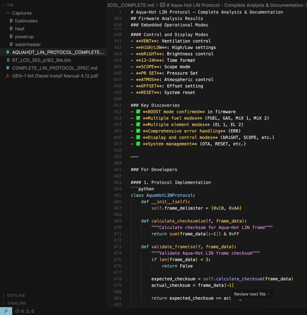
This gave me the exact name of the LCD controller firmware file. Next, I downloaded the MyBluee app local to my mac, then inspected the binary with ChatGPT and within a few moments, I had the direct download link to the firmware:
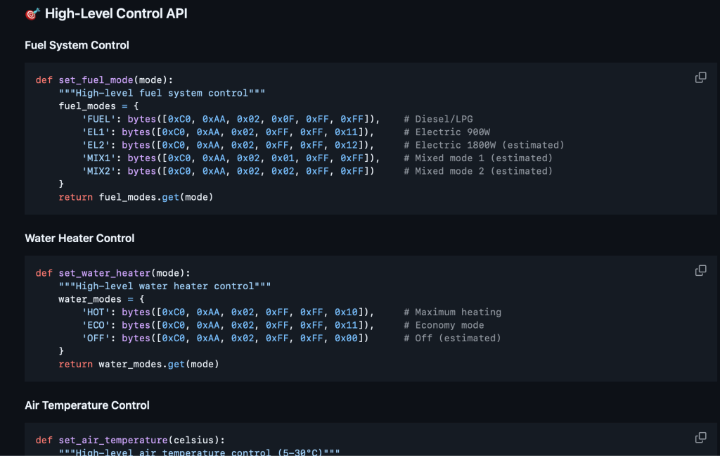
Slapping the bin also into ChatGPT and doing some logic analyzer runs, and boom, I have everything I need to document the bus commands!
There is certainly more work to be done and real world testing, but so much has been accomplished.
Next is to use 2x UART to USB to put UART on TTY and sit in the middle of the LIN to capture data and do command injection. Once done, I’ll throw the UART to LIN on an ESP32 and throw it on MQTT for Home Assistant control 🤌🏻
To control the Combi heater and Heat pump via Home Assistant, I must reverse engineer the communications protocol between the LCD displays and the units. This is more my personal notes.
The Combi does have a RV-C board available.. for $450, which is insane vs the cost of parts.
The primary issue is that the RV-C documentation is not online, and I’ve yet to hear back from them regarding the documentation. It’s worthless without the documentation and I’m waiting to see if it can be run down.
It’s also goofy that they are going from LIN to RS232 then to RS232 to RVC, which smells like off the shelf components.
Reverse engineering basically looks like probing the data lines then logging when operations are performed on the displays, then working out the schema.
Something like this
I have a oscilloscope coming and a Saleae Logic 8 for decoding. It’ll likely end up being a cold winter project. Bringing these into Home Assistant opens lots of automation logic! I just hope the Ecoflow doesn’t end up being a giant pain.
It’s also possible to hack the tuya firmware on the display itself as it is already running an esp32 like microcontroller, would just need to dump the current firmware, I think, to figure out the control scheme.
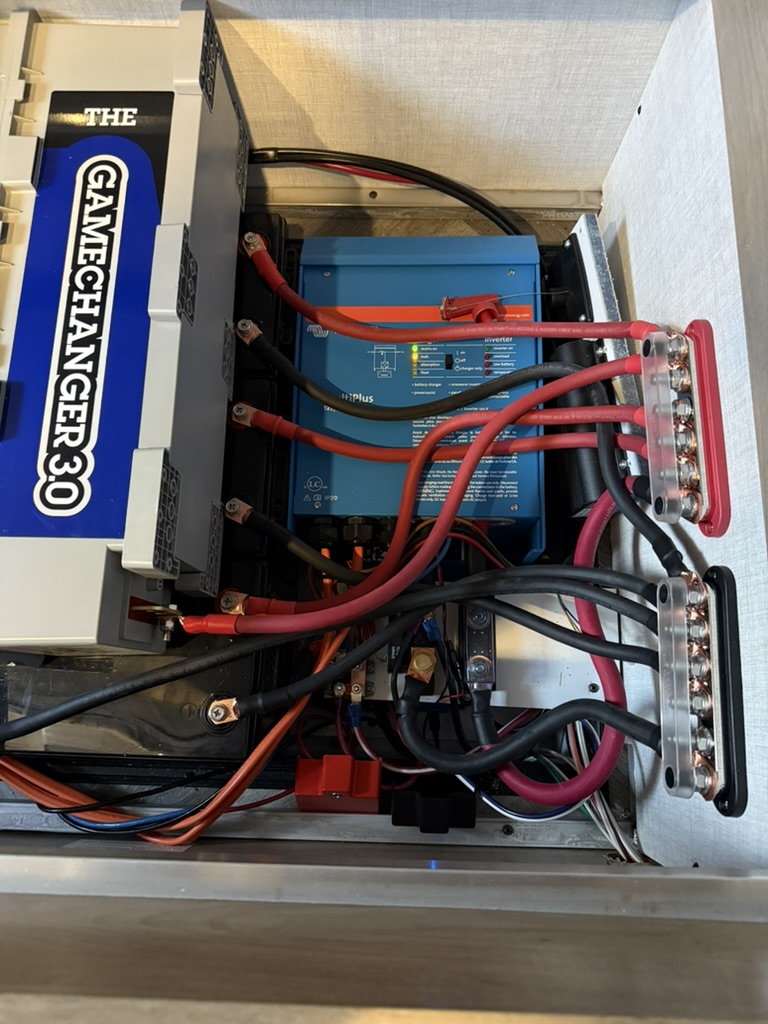
I’ve built my own packs, Victron systems in the past. This time I went with a Delta Pro Ultra with 5x expansion batteries for 30kWh of LifePO4 for a drop in system.
The big downside for me is lack of native integration with Home Assistant for automation, power tracking, etc, however, it seems there are 3rd party hacks out here, such as:
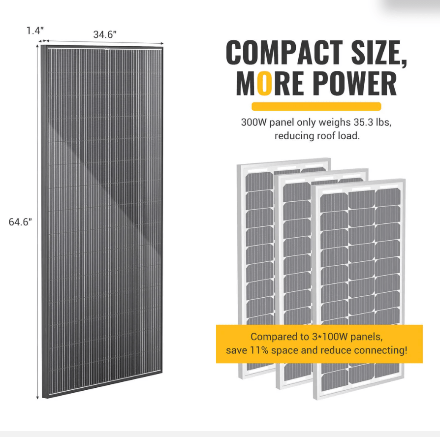
Daily power generation should be around 5kWh a day.
For backup power, I’m using a Honda EU3200i, which has 2,600W running watts:
I wanted something quiet most of all, it works well! Generates about 8kWh per tank of fuel. Only downside is using a rubber belt for the valves, which was stupid of Honda.
The travel trailer I’ll be pulling has 800W of solar and ~13.8kWh if LifePO4, with a Victron setup
The Travel Trailer plugs into the Van for a total of 43.8kWh and 2,000W of solar.
Air conditioning is the major power draw. I’ll go deeper into these systems later
I’ve decided on a multi-layer connectivity setup with WAN failover/load balancing.
Starlink
I don’t need to explain this one, as starlink is widely known, but I went with a Standard dish as I get 300Mbps and more reliable connectivity vs the mini dish as averages 100Mbps. I put it on a strong magnetic mount that’s on a camera ball mount for adjustment. It’s positioned to not shade my panels. it does use about 50W vs 20W between Standard and Mini and snow melt wattage is a thing too.
Running the 5G modem and Starlink off of 12v is more efficient than running it off of 110V.
Spitz AX X3000
Awesome 5G modem! Runs OpenWRT. I’ll be connecting Starlink and running it in bridged mode while using the Spitz as my AP. It’ll be connected to a peplink omni antenna outside of the van which will provide increased signal strength and much better Wifi range outside of the vehicle. As mentioned, I’ll be using WAN failover/load balancing. Most RV sites are shaded with tree cover, Starlink solo doesn’t always work out, and 5G can be faster.
Screenshot
For more permanent setups, Waveform directional antennas are a beast:
I don’t run one right now as I do not plan on being stationary, but have and my speeds went from 100Mbps to 1Gbps on T-Mobile!
That about wraps up comms! Paired with Wi-Fi calling on cell phones, it will be a good, tested setup.
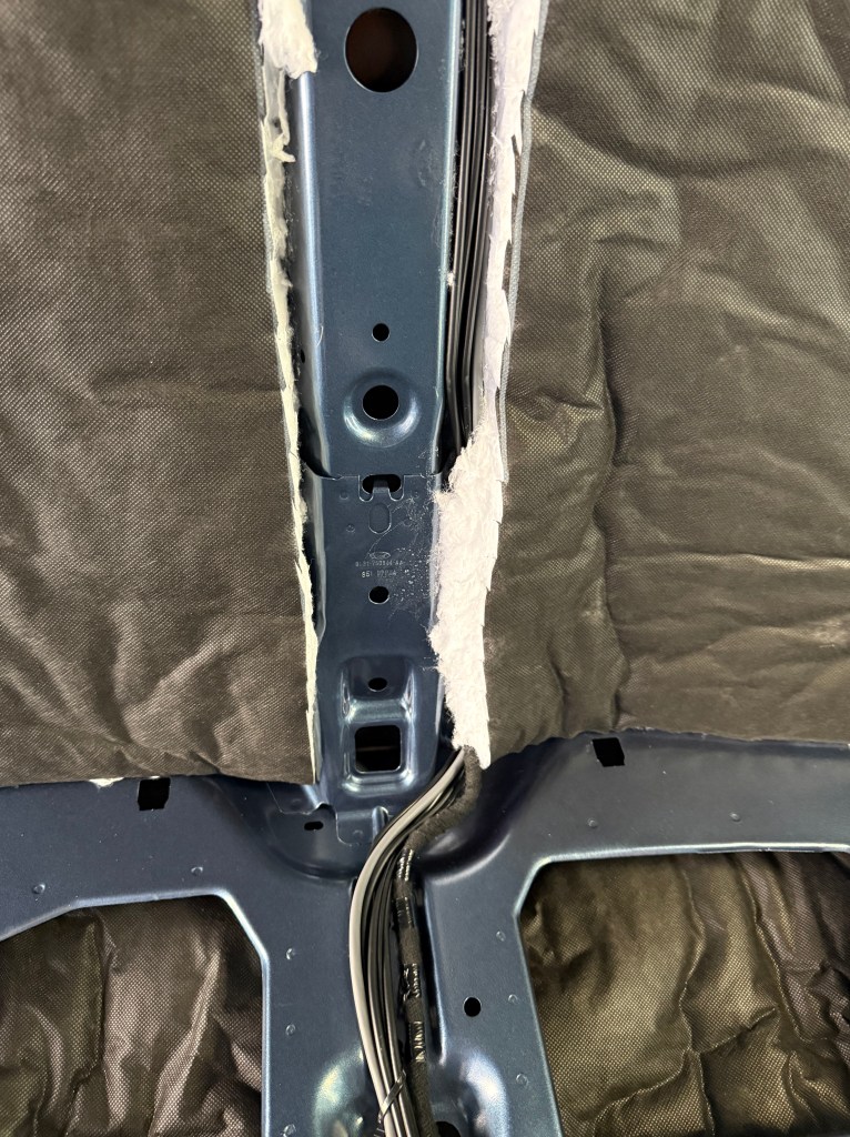
After several builds, this is the first time I’m using Thinsulate. Previously, I used Rock Wool, Fiberglass in my first build (yuck), and XPS foam. I had a decent experience with XPS and Rock Wool, however, Rock Wool is itchy and I bet the loose fibers in the air isn’t too kind to your lungs, especially in an environment exposed to vibration – like a vehicle.
It’s a pleasure to work with! Not itchy and I’m sure I could likely eat it without adverse affects (although I don’t recommend doing such).
70 linear feet was just perfect for all doors, ceiling (including under front headliner), walls (including cubbies) and doubling up on the sides (window cutouts).
Long story short, just as when you put your hand on the metal inside of a vehicle on a hot day, the surface can be very warm to boiling hot. Since I plan on using ACM (Aluminum Composite Material (ACM) Panel) for my ceiling and walls for toughness, I need some sort of thermal break so the walls and ceiling do not become radiators to either the heat, or cool of the outside, especially as I’m playing on hard mode and have a dark painted van.
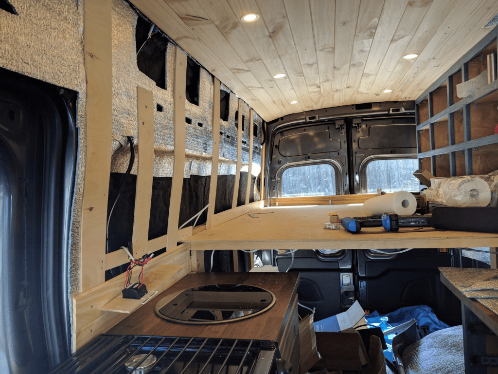
I plan on adhering it to the back of each wall/ceiling panel so it comes off cleanly for maintenance, and for access to wiring without having to adhere it to the van itself. The ACM paneling connects using plastic push pins to existing holes in the van.
This should provide a few benefits. R10 on the sides, which is nice as it’ll be surrounding the bed (and increased noise dampening for sleep and privacy, as Thinsulate is a noise dampening material), R5 of the roof, a radiant barrier all around the ceiling and walls (which will naturally have an air gap in certain areas), and a thermal break. Attaching to the panels should leave minor air gaps for breathability as well, vs encasing the walls/ceiling with the material as you don’t want to seal your insulation in due to condensation, etc for mold reasons.
Overall, this should be a good setup, it would be optimal if my van was white. Reflective/heat insulating window covers are also a 20-30% improvement as the greenhouse effect of the cab on heating is significant.
I will need to figure out some sort of air vent/air mover for cooking, etc – I have not yet and plan on having no windows as of now. I may add them later, but will seek double insulated ones as they are worth it.
Floor insulation is very nice in Winter, I highly recommend it.